


CEM has developed a suite of software tools called CEMWIND, that enable the structural design and analysis of complex filament wound composites. In addition to the structural design/analysis capabilities, the codes allows for evaluation of manufacturing issues and enables the final winding geometry to be transferred directly to the filament winding machine for manufacturing. This software package is ideally suited to the development of composite hubs for high performance rotating machines. CEMWIND addresses three design steps relative to composite hub design that are otherwise difficult and time-consuming using conventional FEA tools:
Generating a composite layup model - Mathematical representation of the filament wound structure – due to the intricacies of filament winding, devising an arbor shape and generating a composite layering scheme from which to fabricate the arbor, does not guarantee that the arbor can be manufactured. Bridging and tow slippage are two phenomena which can occur during winding, thereby preventing an apparently good candidate arbor design from being produced. CEMWIND considers both the mandrel/arbor geometry along with the devised layering scheme, to confirm that the intended structure can be produced on a filament winding machine.
Using a worksheet interface, the arbor designer enters a geometrical description of the underlying mandrel (see Figure 1). This is done, for example, by copying and pasting point locations directly from a CAD drawing of a mandrel. Filament wound composite structures are ordinarily built up in discrete “layers”, CEMWIND works on a layer by layer basis. This means that the selected graphite tow and parameters which direct the winding process (i.e., dictate the fiber path) are layer specific, and from the program computes the detailed geometry of the fully wound layer.
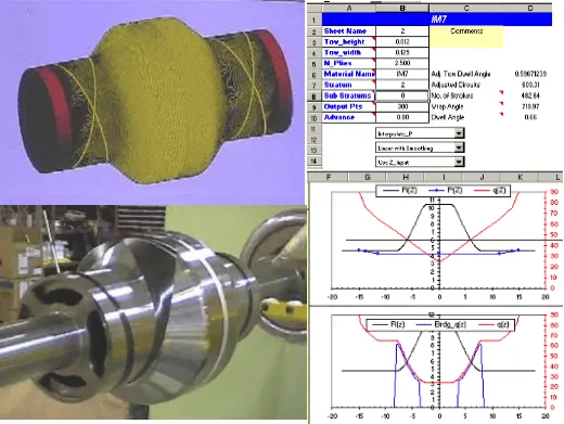
Figure 1: CEMWIND Interface
Several to hundreds of layers may comprise the final composite structure. CEMWIND uses a chaining process, essentially linking the layers together, as each layer is wound onto the growing structure. During each winding step CEMWIND checks for the presence of bridging and/or tow slipping using a friction model. For each layer graphs are provided showing details about winding angle, polar radius function, bridging, margin against slippage, etc.
FEA Analysis - An accurate analysis of a composite arbor requires a detailed FEA structural model capable of fully accounting for the orthotropic material properties of the individual layers within the structure, which can only be derived from an accurate winding layup scheme. For complex structures like arbors, this generally results in each finite element in the model having its own unique set of material properties. When a given arbor winding scheme has been completed, CEMWIND uses a custom algorithm to generate a FEA model, and the resulting model can be analyzed in nearly any FEA package:
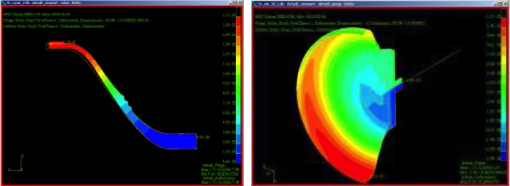
Figure 2: FEA Analysis of Composite Component
The mesh consists of layers of elements conforming to the geometry of the composite layup. Element boundaries are thus constrained to coincide with layer boundaries. Individual finite elements are allowed to span multiple composite layers (few elements, many layers), or there can be multiple layers of finite elements within one composite layer (many elements, few layers). Material properties are calculated using elastic properties, thicknesses and winding angles of the constituent layers within each element. This is done on an element by element basis to produce so-called “smeared” elastic properties in the global axisymmetric coordinate system required for the FE analysis. The use of smeared elastic properties allows a more economical mesh density (compared to modeling each material with its own row of elements), greatly reducing analysis turn-around time.
Post-Processing - In order to apply the most accurate failure models for composite structures, model results for stress and strain must be resolved along the axis of the fiber. Given FEA results from the winding layup structural analysis CEMWIND can post-process these results providing results along the axis of constituent fibers.
After the FE analysis is finished, the results are post-processed in CEMWIND to determine stress and strain information for each layer within the layup. Layer results are first extracted from element results in the global coordinate system used in the FE analysis
Continuity of the strain field permits individual layer strains to be calculated by interpolation within each element. Once the layer strains in the global axisymmetric coordinate system are extracted, they undergo a transformation to produce strain components in the local material principal directions. The fiber direction and transverse strains can at this time be compared to allowable strain limits for the constituent materials to evaluate design margins relative to the material capabilities. Alternatively, the layer strains can be transformed into layer stresses by application of the layer’s constitutive elastic properties and compared to strength data for each layer material. These results for individual layers are in addition to the conventional deformation and strain plots in the global coordinate system produced by the FEA software package.
Contact

Mr. Scott Pish
s.pish@cem.utexas.edu
512-232-1672